NanoPi
The NanoPi is a low power consumption, Samsung S3C2451 based ARM SOC that FriendlyARM developed for Linux hackers, Hobby makers and hobbyists. Its size is only half of the Raspberry Pi(RPi) and its GPIO pins are compatible with the RPi’s. The NanoPi integrates both the WiFi and Bluetooth 4.0,and has a DVP camera interface and an LCD interface. It is easy to run and install Linux/Debian from a TF card. These features make it a good platform for applications in IOT, unmanned vehicles, drones and intelligent devices.
- CPU: Samsung S3C2451, 400Mhz
- RAM: 64M DDR2
- Integrated SDIO WiFi and Bluetooth
- USB Type A x1
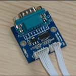
- Debugging Serial Port x1
- microSD Slot x1
- microUSB x1: for power and data transmission. It can be configured as a serial port or Ethernet
- LCD Interface: 0.5mm spacing FPC socket, full color LCD (RGB:8-8-8)
- DVP Camera interface:0.5mm spacing FPC socket. It includes ITU-R BT 601/656 8-bit, I2C and IO
- GPIO1: 2.54mm spacing 40pin, compatible with Raspberry Pi's GPIO. It includes UART, SPI, I2C, IO etc
- GPIO2: 2.54mm spacing 12pin. It includes I2S, I2C, UART etc.
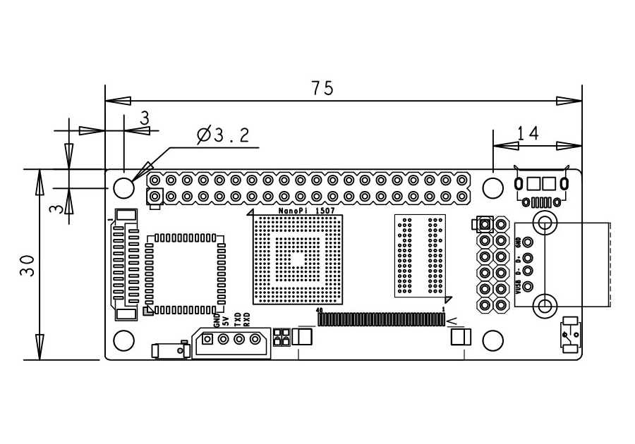
- PCB dimension: 75 x 30 mm
- Power: DC 5V
- Bootloader and OS: u-boot, Linux-4.1 and Debian
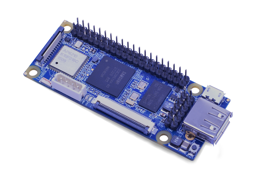
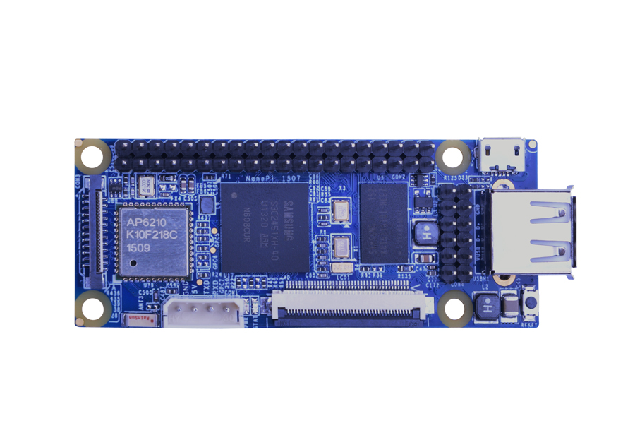
Vertical View (Front)
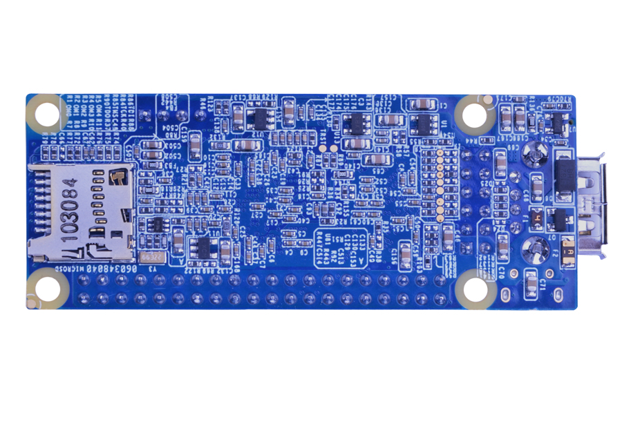
Vertical View (Back)

Dimensional Drawing
Linux
Debian Jessie & Rabbit Linux ReadyWiFi and Bluetooth supported, Python and C ready. Boot the system from a TF card.
| Item | Details |
|---|---|
| Processor | Samsung ARM9 S3C2451, running at 400Mhz |
| Memory | 64MB DDR2, 133Mhz speed |
| Storage | MicroSD Card Slot (up to 32GByte) |
| USB Host | 1 x USB Host 1.1, Type A |
| USB Device | 1 x Micro USB Device 2.0 for power and data transmission |
| LCD (RGB: 8-8-8) |
0.5mm pitch SMT FPC seat, supports full-color LCD |
| Camera | DVP Camera, 0.5mm pitch FPC connector, including ITU-R BT 601/656 8-bit, I2C and IO |
| WiFi | AP6210 SDIO WiFi and Bluetooth integrated on board |
| Bluetooth | AP6210 SDIO WiFi and Bluetooth Integrated on board |
| Power | USB Device Interface |
| Size | 75 x 30 mm |
Quick Start for NanoPi
Development Guide
Resources for NanoPi
By default we ship via CHINA POST. It takes up to one month for CHINA POST to ship. If you want us to ship via DHL/Fedex/TNT/UPS please email us at sales@friendlyarm.com
| Item | Description |
|
|||||||||
|
NanoPi Single Board
|
|
|||||||||
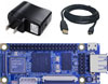 |
NanoPi Development Kits
|
|
|||||||||
OPTIONAL ACCESSORIES

HardWare info for NanoPi
On NanoPi board, it have the follow interface:
- Three UART Serial Port
- Two IIC bus
- One SPI bus
- One IIS interface
- One DVP Camera interface
- One TFT LCD interface
- One Touchscreen interface
- Up to 15 GPIO interface, more interface can be use as GPIO(UART, SPI, IIS, I2C)
More NanoPi interface info, download the NanoPi schematic file.
GPIO1 Pin Define
| Pin# | IC Pin | Note | Pin# | IC Pin | Note |
|---|---|---|---|---|---|
| 1 | VDD_SYS_3.3V | Power Out 3.3V | 2 | VDD_5V | Power In 5V |
| 3 | SDA0 | I2C bus 0 Data | 4 | VDD_5V | Power In 5V |
| 5 | SCL0 | I2C bus 0 Clock | 6 | DGNA | Power GND |
| 7 | GPF1/EINT1 | GPIO with interrupt | 8 | TXD3 | UART3 TXD |
| 9 | DGND | Power GND | 10 | RXD3 | UART3 RXD |
| 11 | EINT2/GPF2 | GPIO with interrupt | 12 | EINT2/GPF3 | GPIO with interrupt |
| 13 | EINT4/GPF4 | GPIO with interrupt | 14 | DGND | Power GND |
| 15 | EINT5/GPF5 | GPIO with interrupt | 16 | TOUT2/GPB2 | PWM2 or GPIO |
| 17 | VDD_SYS_3.3V | Power Out 3.3V | 18 | EINT9/GPG1 | GPIO with interrupt |
| 19 | MOSI0/GPE12 | SPI Bus 0 Master Output | 20 | DGND | Power GND |
| 21 | MISO0/GPE11 | SPI Bus 0 Master Iutput | 22 | TOUT0/GPB0 | PWM0 or GPIO |
| 23 | CLK0/GPE13 | SPI Bus 0 clock | 24 | SS0/GPL13 | GPIO |
| 25 | GND | Power GND | 26 | TOUT1/GPB1 | PWM1 or GPIO |
| 27 | SDA1/GPB7 | I2C bus 1 Data | 28 | SCL1/GPB8 | I2C bus 1 Clock |
| 29 | EINT11/GPG3 | GPIO with interrupt | 30 | DGND | Power GND |
| 31 | EINT12/GPG4 | GPIO with interrupt | 32 | EINT13/GPG5 | GPIO with interrupt |
| 33 | EINT14/GPG6 | GPIO with interrupt | 34 | DGND | Power GND |
| 35 | EINT15/GPG7 | GPIO with interrupt | 36 | EINT16/GPG8 | GPIO with interrupt |
| 37 | EINT17/GPG9 | GPIO with interrupt | 38 | EINT18/GPG10 | GPIO with interrupt |
| 39 | DGND | Power GND | 40 | EINT19/GPG11 | GPIO with interrupt |
GPIO2 Pin Define
| Pin# | IC Pin | Note | Pin# | IC Pin | Note |
|---|---|---|---|---|---|
| 1 | VDD_5V | Power In 5V | 2 | VDD_SYS_3.3V | Power Out 3.3V |
| 3 | TXD2 | UART2 TXD | 4 | RXD2 | UART2 RXD |
| 5 | SDA0 | I2C bus 0 Data | 6 | SCL0 | I2C bus 0 Clock |
| 7 | IIS-SDO0 | IIS 0 Audio serial data output | 8 | IIS-SDI0 | IIS 0 Audio serial data input |
| 9 | IIS-SCLK0 | IIS 0 Audio serial clock | 10 | IIS-LRCK0 | IIS 0 Audio channel select clock |
| 11 | IIS-CDCLK0 | IIS 0 Audio Codec clock | 12 | DGND | Power GND |
RGB LCDIF Pin Define
| Pin# | IC Pin | Note |
|---|---|---|
| 1,2 | VDD_5V | Power Out/In 5V |
| 11,20,29 | DGND | Power GND |
| 3-10 | Blue LSB to MSB | TFT LCD Blue Signal |
| 12-19 | Green LSB to MSB | TFT LCD Green Signal |
| 21-28 | Red LSB to MSB | TFT LCD Red Signal |
| 30 | GPJ12 | IO |
| 31 | GPG2 | IO |
| 32 | XnRSTOUT From CPU | Reset signal |
| 33 | VDEN | Data Enable |
| 34 | VSYNC | Vertical Sync. Signal |
| 35 | HSYNC | Horizontal Sync. Signal |
| 36 | LCDCLK | LCD Video Clock |
| 37-40 | XM,XP,YM,YP | Touchsreen Signal |
DVP Camera IF Pin Define
| Pin# | IC Pin | Note |
|---|---|---|
| 1,2 | VDD_SYS_3.3V | Power Out 3V |
| 7,9,13,15,24 | DGND | Power GND |
| 3 | SCL0 | I2C bus 0 Clock |
| 4 | SDA0 | I2C bus 0 Data |
| 5 | GPH13 | IO |
| 6 | GPJ12 | IO |
| 8 | XCLK | Clock |
| 10 | NC | No Connector |
| 11 | VSYNC | sync signal |
| 12 | HREF | HREF |
| 14 | PCLK | PCLK |
| 16-23 | Data bit7-0 | Data bus |
Debug Port CON1(UART0)
| Pin# | IC Pin | Note |
|---|---|---|
| 1 | DGND | Power GND |
| 2 | VDD_5V | Power Out/In 5V |
| 3 | TXD0 | UART0: Debug serial Port TXD |
| 4 | RXD0 | UART0: Debug serial Port RXD |
Quick Start for NanoPi

1. Quick Start for NanoPi
1.1 What you will need
- One NanoPi Board
- MicroSD/TF Card - Recommend an 8GB MicroSD card, you can buy a card with linux system pre-install, or install the system with the follow step.
- MicroUSB Cable
- a Host running Ubuntu and connected to the internet
1.2 Created a MicroSD Card with Debian system
- Insert your microSD card to your host running Ubuntu and check your SD card's device name.
dmesg | tail
Search the messages output by "dmesg" for similar words like "sdc: sdc1 sdc2". If you can find them it means your SD card is recognized as "/dev/sdc". Or you can check that by commanding "cat /proc/partitions". - Flash Firmware to MicroSD Card
git clone https://github.com/friendlyarm/sd-fuse_nanopi.gitcd sd-fuse_nanopisu./fusing.sh /dev/sdxNotice: replace the /dev/sdx to your MicroSD card inode.
1.3 Run the system
- Insert the MicroSD system card into the NanoPi.
- Connect the MicroUSB cable from PC to NanoPi, the NanoPi will boot the debian system auto.
- when the NanoPi Blue LED light on, it means the NanoPi have run the system success.
2 Play with the NanoPi
2.1 Using the SSH session via USB Cable Connect
- Connect the Micro USB cable, and the NanoPi have run the system.
On the PC command line, run the dmesg command, then you will get the follow info, then it means connect success,[12601.100339] usb 2-1.7: Product: FriendlyARM Gadget v2.4 [12601.100343] usb 2-1.7: Manufacturer: Linux 4.1.2-FriendlyARM with s3c-hsudc [12601.103192] cdc_acm 2-1.7:2.0: This device cannot do calls on its own. It is not a modem. [12601.103368] cdc_acm 2-1.7:2.0: ttyACM0: USB ACM device [12601.105300] cdc_ether 2-1.7:2.2 usb0: register 'cdc_ether' at usb-0000:00:1d.0-1.7, CDC Ethernet Device, 46:a1:e7:6d:5c:32
- If you run the command "ifconfig", you will find the usb0, then you can connect it with the SSH command to login the NanoPi(192.168.100.1):
ssh root@192.168.100.1
It required the password, input the password fa.
2.2 Configure the WiFi connection
- After you connect the board by SSH(The default system is Debian), then run the follow command to check the WiFi device:
ifconfig -a
If the Wlan device is wlan0, you should create the same name file "wlan0" in the /etc/network/interfaces.d/, as the follow command:vi /etc/network/interfaces.d/wlan0
Add the follow content in wlan0auto lo iface lo inet loopback auto wlan0 iface wlan0 inet dhcp wpa-driver wext wpa-ssid YourWiFiESSID wpa-ap-scan 1 wpa-proto RSN wpa-pairwise CCMP wpa-group CCMP wpa-key-mgmt WPA-PSK wpa-psk YourWiFiPassword
Notice: the "YourWiFiESSID" is your WiFi AP name, "YourWiFiPassword" is your WiFi Ap password, replace it. then save the file and restart the Network as the follow command:/etc/init.d/networking restart
Then it will connect the WiFi AP when boot the system. - If you use the Rabbit linux system run the follow command the configure the WiFi.
wpa_passphrase YourWiFiESSID 'YourWiFiPassword' >> /etc/wpa.conf
wpa_cli -iwlan0 reconfigure
Notice: The WiFi Router name is YourWiFiESSID , the password is YourWiFiPassword, after you configure it, the board will save the wifi configure info, and will connect the WiFi auto when boot the system for everytime, if you want the change the WiFi saved configure, you can edit the file "/etc/wpa.conf" to reset the WiFi info.
The default WiFi connecttion configure is DHCP, if you want to configure the wifi with static IP, you can edit the /usr/sbin/wpa_action, and replace the "udhcpc" to "ifconfig" command. For the DHCP or Static IP demo in the /usr/sbin/wpa_action, click here to see the demo file. -
If you want to scan the WiFi AP device, run the follow command to Scan it:
wpa_cli -iwlan0 scan
wpa_cli -iwlan0 scan_result
2.3 Install the Debian software package
- We provide the stand Debian jessie, you can run the apt-get to install the software, for the first time, you can udpate the source list as follow command:
apt-get update
- Then you can install the software as follow, such as install the ftp server
apt-get install vsftpd
NanoPi development Manual
1.1 Download and uncompress the ARM Cross Compiler
1.2 Update the u-boot.bin to MicroSD card
2.1 Download and Build U-Boot
2.2 Install Cross-Compile tools
3.1 Download and Build Linux kernel
3.2 Build the Linux Kernel Module
4.1 Build the Debian file system
4.2 Create the Rabbit Linux
5 Created a MicroSD Card with Compiled system image
5.1 Created the MicroSD card
5.2 Update the U-boot Boot Parameter
1. Setup ARM Cross Compiler
1.1 Download and uncompress the ARM Cross Compiler
- Run the follow command to download the Cross Compiler from our git webserver.
git clone https://github.com/friendlyarm/prebuilts.gittar xvzf prebuilts/gcc/arm-linux-gcc-4.4.3.tar.gz -C /
1.2 Install Cross-Compile tools
- Modify your ~/.bashrc file to add a new path with editor (gedit or vi)
gedit ~/.bashrc
- add the follow into the .bashrc file
export PATH=/opt/FriendlyARM/toolschain/4.4.3/bin/:$PATH
- To apply this change, login again or restart the .bashrc
source ~/.bashrc
2 Build U-Boot from sources
2.1 Download and Build U-Boot
- You can easily download U-Boot source code from FriendlyARM GitHub U-Boot repository.
- clone the GitHub U-Boot repository, and Build U-Boot binary.
git clone https://github.com/friendlyarm/uboot_nanopi.gitcd uboot_nanopigit checkout nanopimake nanopi_configmake
The result of these operations is a fresh U-Boot binary called u-boot.bin
2.2 Update the u-boot.bin to MicroSD card.
- If you want to test the u-boot.bin, you can use the shell fusing.sh to do it, if your MicroSD card inode is /dev/sdd, then do it with root user as the follow command:
su./fusing.sh /dev/sdd
3 Build Linux Kernel
3.1 Download and Build Linux kernel
- clone the GitHub Kernel repository, and Build Kernel binary.
git clone https://github.com/friendlyarm/linux-4.x.y.gitcd linux-4.x.ygit checkout nanopi-v4.1.ymake nanopi_defconfigtouch .scmversionmake
The linux kernel Branch for NanoPi is nanopi-v4.1.y, you should switch the branch to nanopi-v4.1.y, then build it, you will get the kernel programming file arch/arm/boot/zImage.
3.2 Build the Linux Kernel Module
- When the linux kernel was compiled, some kernel module file(such as ipv6, netfilter) were built default, it have created the ko file.
- If you want to add or edit the kernel module, you need compile the kernel module and compress it as kernel-modules.tgz file, and replace the basefs/kernel-modules.tgz on the Rootfs folder.
- Run the followed command with root user, install the .ko file to /tmp/nanopi-modules
make INSTALL_MOD_PATH=/tmp/nanopi-modules modules_install - Then strip the Linux kernel module, creat the compress lib
cd /tmp/nanopi-modules/lib/ find . -name \*.ko | xargs arm-linux-strip --strip-unneeded tar czvf kernel-modules.tgz modules/
- If you want to test the new kernel module, uncompress the kernel-modules.tgz to lib folder on the nanoPi MicroSD system Card.
rm -rf /media/fa/NANOPI/lib/modules/ tar xzvf kernel-modules.tgz -C /media/fa/NANOPI/lib/
The Rootfs Partition on the MicroSD card was mount on the /media/fa/NANOPI folder.
4 Created the File system
4.1 Build the Debian file system
- The pre-install Debian system is the standard debian insatll package, you can download with the follow command
git clone https://github.com/friendlyarm/sd-fuse_nanopi.gitcd sd-fuse_nanopi/prebuilt/ ls -l rootfs.tgz - If you want to do your own Debian system, you can upcompress the rootfs.tgz and edit it, then recompress it again, such as install a deb software package with the follow command:
tar xzf rootfs.tgz dpkg -i --force-all --root=./rootfs /tmp/qtembedded-4.8.5_armel.deb tar czf rootfs.tgz rootfs
4.2 Create the Rabbit Linux
We provide a sample file system, we called it as Rabbit Linux, If you want to build it, you can run the follow command:
- User the root user, then Download the Rootfs source code and Build it
git clone https://github.com/friendlyarm/rootfs_nanopi.gitcd rootfs_nanopigit checkout nanopisu make && make install && make strip
- When build success, it will show the follow info
RootFS (core) successfully installed to:
   /tmp/FriendlyARM/nanopi/rootfs

Copyright 2015 FriendlyARM (http://www.arm9.net/)
- The above info show the rootfs was created on the /tmp/FriendlyARM/nanopi/rootfs folder, we compress it
cd /tmp/FriendlyARM/nanopitar czvf rootfs.tgz rootfs/
5 Created a MicroSD Card with Compiled system image
5.1 Created the MicroSD card
- Download the SD card Tools lib, and switch it to master branch.
git clone https://github.com/friendlyarm/sd-fuse_nanopi.gitcd sd-fuse_nanopigit checkout master
- The system image was in the prebuilt folder(The prebuilt folder was in the sd-fuse_nanopi folder).
>>u-boot.bin : System Bootloader image file
>>sdenv.raw : U-boot Boot Parameter, for booting the system
>>zImage : Linux kernel image file
>>rootfs.tgz : the Root file system compress lib
Replace them with your compiled system image file, then run the follow command on the sd-fuse_nanopi folder:su./fusing.sh /dev/sdxNotice: the /dev/sdx was your MicroSD card inode on the PC - Then insert the MicroSD card to the NanoPi, try it.
5.2 Update the U-boot Boot Parameter
- If you update the U-Boot boot Parameter on the U-Boot command line, and want to use it in the new SD card, you should save it and replace the sdenv.raw file in the Rootfs prebuilt folder.
./readenv.sh /dev/sddcp sdenv.raw prebuilt/
Connect camera module
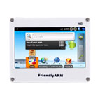
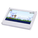
Connect LCD TFT
Connect Matrix starter DIY Suite
Make a 4.3 inch computer
Making wireless smart car
Buy Now
| Item | Description |
|
|||||||||
|
NanoPi Single Board
|
|
|||||||||
|
NanoPi Development Kits
|
|
|||||||||